


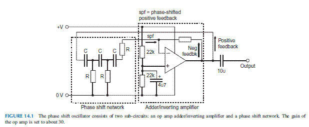
First thing to know is that all three oscillators depend on +ve feedback to keep them oscillating. Some part of the output produced by the op amp is required to be fed back to its non-inverting input to keep itself in the oscillations.
The voltage level at the +ve terminal of the op amp is kept constant at half the supply, and stabilized by making use of capacitor.
A rising voltage at the output is fed back to the inverting inputs (2) that as a result cause a fall of output. This is +ve feedback and the op amp would have as table output. Also there is +ve feedback across the phase shift network.
The network contains 3 high-pass filters connected in series. It is made clear that the output from allow-pass filter lags behind the input by approximately 90 degrees. On the contrary the output of a high-pass filter leads input by approximately 90 degrees.
These 3 filters can produce a phase lead of up to 270 degrees. At a particular frequency the lead will be 180 degrees. The signal that is passing through the phase-shift network is fully out of phase with the op-amp output. This signal is now amplified and inverted by the op amp, so it is in phase with the -ve feedback signal. The output from the circuit is unstable and oscillates strongly.
The output waveform is a sinusoid with frequency determined as
f = 1/15.39RC.
The circuit we discussed is simple designed that is most excellent used as a fixed-frequency oscillator. It will be harder to have connected variable resistors or capacitors in the network and tuning them simultnously.


0 comments:
Post a Comment