Showing posts with label ac circuit diagram. Show all posts

Temperature coefficient of resistance


It is normal when the temperature of a material increases, the resistance increases in the most of conductors, insulators decrease in resistance, whilst the resistance of some special alloys remains almost constant.

The temperature coefficient of resistance of a material is the increase in the resistance of a 1OHM resistor of that material when it is subjected to a rise of temperature of 1C. Greek alpha is the symbol which is used for the temperature coefficient of resistance is “α”.

Thus, if some copper wire of resistance 1OHM is heated through 1C and its resistance is then measured as 1.0043OHM then α=0.0043Ω/ΩC for copper. The units are normally expressed only as ‘per C’, i.e. α=0.0043/Cfor copper. If the 1Ω resistor of copper is heated through 100C then the resistance was at 100C would be 1+100x0.0043=1.43Ω_.
Read More!

Field effect transistors


We can find Field effect transistors in 2 basic forms; junction gate & insulated gate. The gate source junction of a junction gate field effect transistor (JFET) is well a reverse-biased p-n junction.The gate connection of an insulated gate field effect transistor(IGFET), on the other end is insulated from the channel and charge is capacitively coupled to the channel. To keep matter simple, only JFET devices are considered in this tutorial. Diagram below presents the basic structure of an n-channel JFET.
Read More!

Purely inductive a.c. circuits

Read More!

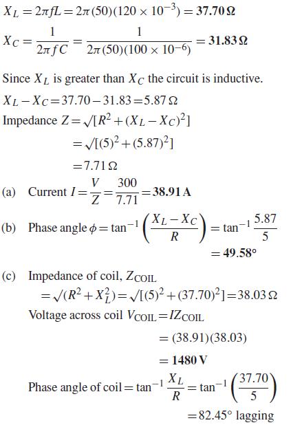
R–L–C series a.c. circuit


Read More!

RC series a.c circuits

Read More!

Read More!

 
Design by Wordpress Theme | Bloggerized by Free Blogger Templates | coupon codes